Experiments·
Amp Funnel Coil Powers 8 Neo Cube Magnet Pulse Motor to 1300 RPM
Watch me run an 8 neo cube magnet pulse motor up to 1300 RPM using an amp funnel coil. Real bench tests, scope shots, voltage readings and what actually happens with this funnel coil power setup.
Long-form · Full audio · Best on YouTube
Watch the complete video: Amp Funnel Coil Powers 8 Neo Cube Magnet Pulse Motor to 1300 RPM
Watch the full long-form video on YouTube — that's where the full bench audio, runtime, and experiments live.
See it on the bench · full runtime on YouTube
What to watch for
- ▸The amp funnel coil is wound 28 gauge in the center stepping to 26 then 24 gauge on the outer rim, acting like a current megaphone.
- ▸Eight neo cube magnets on the rotor produced smooth running and charged a 500F 16V capacitor bank at a decent rate through a bridge rectifier.
- ▸Scope showed 500 peak-to-peak volts from the induction coil behind the drive coil; the bottom spike disappears at higher speeds, losing about 200V p-p.
- ▸The setup runs as a flywheel for 8-9 minutes once spinning even with no input power, though induction loads it down.
- ▸AC voltage readings reached 100-116V; the motor-generator lights bulbs from the drive coil while induction coils generate power.
Watch the full long-form video on YouTube — that's where the full bench audio, runtime, and experiments live.
Experiment notes
I built a motor generator with an 8-magnet rotor using neo cubes and an amp funnel coil on the generation side. It hits around 1300 RPM before the shaft shakes. We measured AC voltage, looked at the oscilloscope waveforms, charged a capacitor bank, and isolated induction from different coils. The funnel coil starts with thinner wire in the middle and steps up to thicker on the outside.
Key takeaways
- The amp funnel coil is wound 28 gauge in the center stepping to 26 then 24 gauge on the outer rim, acting like a current megaphone.
- Eight neo cube magnets on the rotor produced smooth running and charged a 500F 16V capacitor bank at a decent rate through a bridge rectifier.
- Scope showed 500 peak-to-peak volts from the induction coil behind the drive coil; the bottom spike disappears at higher speeds, losing about 200V p-p.
- The setup runs as a flywheel for 8-9 minutes once spinning even with no input power, though induction loads it down.
- AC voltage readings reached 100-116V; the motor-generator lights bulbs from the drive coil while induction coils generate power.
I put together this motor generator with one drive coil and multiple induction coils plus an amp funnel coil. The rotor uses eight neo cubes and it really surprised me how well it performed. We got it up to 1300 RPM before vibration kicked in. The funnel coil on the generation side gave us solid voltage and we watched the waveforms on the scope. It runs for minutes like a heavy flywheel once you get it going. Pretty cool bench session overall.
Related on this site
- Pulse Motor Rotor Design: Magnets, Materials and Balance — Directly relates to the 8-magnet neo cube rotor and balance discussion in the transcript
- Best Neodymium Magnets for Pulse Motor Rotors — Compares neo cube magnets to rectangle magnets as mentioned on the bench
- Reading Oscilloscope Output on a Pulse Motor — Matches the multiple scope captures and waveform explanations shown
- Best Wire Gauge for Pulse Motor Coils (AWG Guide) — The funnel coil uses specific 28-26-24 gauge stepping that fits the wire gauge experiments
- How to Maximize RPM on Your Pulse Motor — We reached 1300 RPM and noted the vibration limit, directly relevant to RPM testing
---
*Generated from video transcript (hash `73a183ab8a63…`).*
Full transcript
Hello, ladies and gentlemen. What's up? It's Papa Bale and welcome to the channel. Um I like messing around with with magnets, magnetic field. Uh this is a motor generator. Okay, let's see. We got one drive coil right here. This is uh 300 turn. It's actually 900 turns all together in parallel. So, it's 300 turns of 20, 18, and 32 for the trigger. Uh that's a 18 or not an 18, but a eight magnet rotor. Um they're neo cubes. Uh honestly, when I put them all together, I I didn't think I was going to get that much juice out of it, but I was wrong. All right, this is an amp funnel coil that starts in the middle at 28. And it goes 26, uh a little bit thicker, and then 24 on the outer rim there. And uh that's a it's a amp megaphone kind of thing. If you think of it as a cone, it starts small current-wise and ends big. Uh now I know that the current is uh what do you call it? Limited by the smaller strand or the thinnest strand. But, there's a lot of benefit to having thicker wire. Um But, this this coil is on the generation side. I put 50 V through this to run it as a drive coil, and then we only got like 400 RPMs. But, it did work. It worked very well. Uh just not not as fast as I like. Uh there's 32 gauge coil on the end there. And then this one's 24 and 32. It's a thin induction coil. See how many layers it has? But then it's only it's very thin. All right. So, this this coil on the end here is 32-gauge and 26-gauge. All right. So, there's our oscilloscope. Let me reset this. We're going to start with our uh our voltage, AC voltage. So, I got I got the multimeter hooked up to the coils. I have a bridge rectifier for each set, but I have the meter hooked up to the coils. So, we got a AC reading. Okay, here's the wave I'm looking for, the clip. And got a boomsky. Now, I'll stop it. Now, the indu- the coil uh the drive coils was lighting the light. So, all the amps and the go through the coil, the drive coil here, go to the light. Now, all the induction coils are here. You can hear that thing rev up, man. That is awesome. >> All right, we're going to stop it. Our Our shaft is shaking, so we're going to stop it. We're going to change this to a telescope. Oscilloscope. Boom, look at that. All right. I'm going to let it simmer down a little bit cuz I'm going to start it up again. This thing will run like that for not exactly like that, but it'll run pretty fast for a good 8 minutes, 9 minutes. But it's constantly slowing down since there's no power going through it right now. It's more like a flywheel right now. A flywheel that can generate electricity with the magnets that's making it heavy. All right, so this coil right here with the blue tape is a little different. It's behind the drive coil. So, when the drive coil when magnet passes the drive coil and it gets initiated, um this is going to pick up some heavy induction and you'll see it on the oscilloscope. All right, and you see how it's nice and smooth right there? Look at that. And that's all due to this coil. 500 peak-to-peak. But this will get going fast enough that that bottom spike will cut off. There it goes. You see it you Did you see how it like disappeared on the bottom? Yeah, that I don't know what that is, but it it kind of sucks cuz it you lose about 200 volts peak to peak. And that's awesome. Well, losing the voltage is not awesome, but this this setup here is pretty freaking cool. I mean to isolate the difference in induction is you know, win in and of itself. There are those of us who know Excuse me, I had to pick this up. There There are those of us who know about this and then there are those of us who learn about this. This is the wave that's coming off of the magnets uh from you know, the magnets hitting each one of these three coils. It's a little far away to hit this coil unless it's going fast. So, we we know that the induction from this coil is coming from the drive coil. So cool. >> And then the light flickers and the negative goes away. Look at that thing go. That is awesome. For eight magnets, that's powerful, man. I mean, if you tried to stop that thing with your hand, you'd lose a finger. So, I say it gets that right around 1,200 RPMs, 1,300 RPMs, and then this the shaft starts to shake. And I got it is pretty much as centered as it's going to be. Uh I'm not sure where the It's probably just cuz it's a circle. And you know the what they say about a perfect circle. All right, let's get one more reading. An AC reading. There's 100 V. It's going to go about 116 V. Now, I have two rotors that have eight magnets capabilities. I have the rectangle magnets and I have the cubes that I have here. I know the rectangle magnets will give me give me way more insane readings than than the cubes. But the yeah, this is really smooth. And this thing runs like a flywheel when the power's not on, even though it's being loaded down kind of by induction. Got one more thing I want to show you. Actually, no. Um this meter was hooked up to the cap bank. And when I plug uh the coils into the bridge rectifier that's hooked to the cap bank, uh I can charge with induction the cap bank at a pretty decent rate. Um for induction, that is. Now, if I hook the coil to the cap bank, I can load it up in a minute. And that's 500 F 16 V right there. Right there. All right. Well, thank you very much, ladies and gentlemen. It's been awesome. Peace out. Have a wonderful day. Uh please be inspired to build stuff. Bye now.
Keep watching · longer sessions
More long-form bench runs
Queue up the next long-form bench run on YouTube — longer sessions keep the workshop free for everyone.
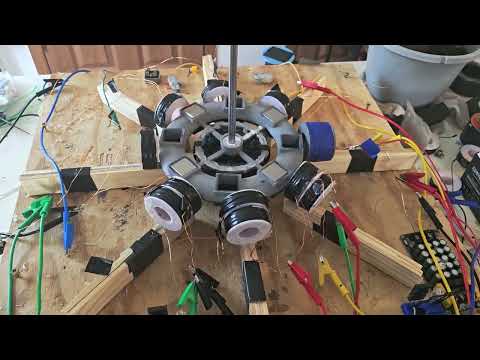 Long-form
2 circuits running a third room still for some growth/expansion.
Papa Bale here with a messy bench update.
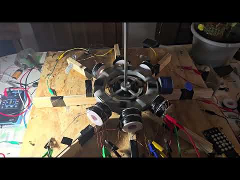 Long-form
M.P.H.'s pulse motor labs EP:2 Skin deep
I fire up two circuits at once, chase meter spikes, and retell the day a three magnet rotor one literally exploded at speed.
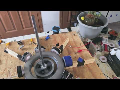 Long-form
Amp Funnel Coil: Pulse Motor Labs EP:1
Eight-magnet eight-coil pulse motor lab — amp funnel coil wiring, pickup coils, and give-and-take battery measurements.
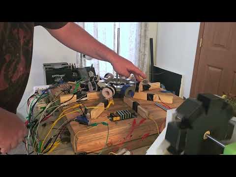 Long-form
MPH pulse motor lab
Real bench time with motor rotor magnets on a pulse motor rotor.
One path · free first
Watch free → subscribe → optional membership
Notes stay free. The full experiment lives on YouTube. Membership is optional when you want Discord and exclusives — not required to learn.
- 2
Subscribe free + turn on alerts
Hit Subscribe, then the 🔔 bell so you catch the next experiment.
Subscribe free + 🔔