Experiments·
Parallel Drive Coils Pulse Motor: 4 Coils, 25x Gain, 2V In 55V 1A Out
Watch me run a parallel drive coils pulse motor with 4 coils in cardinal directions on one reed switch. Real bench readings: 2.08V 0.7A input, 55V 1A output. Lots of different coil wire gauges and turns. Curious low-frequency results and what happens when you add voltage.
Long-form · Full audio · Best on YouTube
Watch the complete video: Parallel Drive Coils Pulse Motor: 4 Coils, 25x Gain, 2V In 55V 1A Out
Watch the full long-form video on YouTube — that's where the full bench audio, runtime, and experiments live.
See it on the bench · full runtime on YouTube
What to watch for
- ▸Four parallel drive coils on one reed switch in north-south-east-west positions
- ▸Input around 2.08-2.8V at 0.6-0.7A produces 46-55V DC at 1-1.2A output
- ▸Heavy mix of coil wire gauges and turns (250 to 18,000) creates lots of iron and current
- ▸Frequency stays very low at 41-42Hz even as voltage climbs
- ▸Adding voltage can slow the rotor due to magnetic fluctuations
- ▸All output comes from moving magnets past the generator coils
Watch the full long-form video on YouTube — that's where the full bench audio, runtime, and experiments live.
Experiment notes
I hooked four coils in parallel on a single reed switch for this pulse motor generator build. Using a mix of 16, 18, 20, 22, 26, 30, 32 gauge wires with hundreds to 18k turns, we see low frequency output around 41-42Hz, DC voltages fluctuating 35-56V at about 1A while input stays under 3V and under 1A. The motor slows when voltage increases too much due to magnetic drag from all the iron. It's putting out way more than we're putting in on the bench.
Key takeaways
- Four parallel drive coils on one reed switch in north-south-east-west positions
- Input around 2.08-2.8V at 0.6-0.7A produces 46-55V DC at 1-1.2A output
- Heavy mix of coil wire gauges and turns (250 to 18,000) creates lots of iron and current
- Frequency stays very low at 41-42Hz even as voltage climbs
- Adding voltage can slow the rotor due to magnetic fluctuations
- All output comes from moving magnets past the generator coils
I fired up the bench with four coils wired in parallel on a single reed switch. The goal was simple — see what kind of numbers we get when everything triggers together on one drive circuit.
The input side stayed low: we were feeding between 2.08V and 2.8V at 0.6-0.7A most of the run. On the output side the bridge rectifier showed 35-56V DC fluctuating and right around 1A. That’s a solid gain on paper.
Frequency on the scope was very low, 41-42Hz. Even when I pushed the voltage the waveform stayed slow. The rotor has a four-magnet setup and all that iron in the coils makes the magnetic environment pretty busy.
I used a mix of wire on the generator side — 20 gauge, 22, 26, 30, 32 gauge — plus one coil with 18,000 turns of 32 gauge that measured over a kiloohm. The drive coils are mostly 16 gauge with 250 turns each and one 20 gauge with 666 turns. One has a 30 gauge trigger strand ready for when the transistor shows up.
When I bumped voltage by half a volt the rotor slowed down hard. I had to dial it back. Too much juice on one reed switch with all that iron creates drag. Later I’ll split the cardinal directions onto separate parallel circuits with transistors so they fire bang-bang instead of all at once.
Everything you see coming out is just magnets moving past coils. No magic, just induction. The thick wire seems to help pull more amperage on the output. I’m impressed we’re getting over an amp out while staying under an amp in.
Bench notes: readings jumped around when I adjusted voltage. One rectifier was flaky so I swapped. Rotor speed recovered when I dropped back to 2.6V. All DC after the bridge. Lots of iron, lots of wire, low frequency, decent gain on the table.
Related on this site
- Best Wire Gauge for Pulse Motor Coils (AWG Guide) — Directly addresses the mix of 16-32 gauge coil wire used and why thick wire helped amperage
- Pulse Motor vs Bedini Motor: What's the Difference? — Viewer asked why it’s called a pulse motor; transcript explains pulsing on/off sequence
- Pulse Motor Rotor Design: Magnets, Materials and Balance — Four-magnet rotor and magnetic drag from iron discussed in the test
---
*Generated from video transcript (hash `953405e401fe…`).*
Full transcript
hello ladies and gentlemen what's up this is Papa Bale and welcome to the channel um what we're looking at over here is what I'm generating currently off of this system so we got uh these are this is all DC fluctuation between 35 and 55 56 DC volts and about an amp of DC current and what we're putting in is 2.4.5 volts and in between 1 and 7 or 6 7 of an amp so technically we are generating more by a lot uh of DC electricity so the electricity is the same uh let's take a look at frequency is at 41 though 42 very low frequency very low voltage this is what's coming off the bridge rectifier right here I'm about to put some more juice into it about 43 DC volts are going in are coming out I mean in about 0.9 900 milliamps okay that's how much is coming out this one's kind of broken you know so we're going to do the one that's more sturdy and then we'll get a another look at the wave here it's very low frequency though we're going to turn it up the wattage a little bit though we're going to see where it starts to uh we might not get that high so this is 2.7 at 1 amp 54 DC volts very cool 55 1.2 see we're generating a lot more current with this than we would with other Motors cuz I'm I'm using 20 gauge as a generator I'm using 22 gauge 30 gauge 32 gauge 26 gauge it's all in there lots of iron yeah lots of it yeah lots of it so about 55 volts of DC so this is a this is a four coil parallel circuit so all the cardinal directions right here north south east and west are all hooked up to this read switch and we're pulling uh between 0.5 and 7 right now I want to get a tack reading real quick oh we're starting to slow down hardcore maybe that's too much juice for the switch right now it's alling out red stone yep what's red stone that's that's what the wir made out H we're speeding up cool speeding up speeding up so that's interesting how you increase the voltage by like0 five of a volt and it starts to slow down when you got all four hooked up to one read switch with all that iron in there we're getting kind of uh magnetically fluctuating ratings so right around 400 right now drop it just a little bit more two 2.6 well know if I'm going the right way no well I don't know yet so I'm going to be making a motor 400 I think we're in the right direction I'm going to be making a motor that is going to have one drive coil and it's going to have well I'm going to be making two Motors maybe three motors first motor is going to be this one right here but we're going to hook up the cardinal directions and then we're going to shift it and we're going to hook up the other cardinal directions on parallel circuits on uh transistors which should be coming pretty soon and then when we trigger both of them at uh one after the other it'll be a four magnet rotor so it'll go bang bang that speed is going to get it'll double up at least from all of it's coming out of a wire out of a wire that that's right that's that's absolutely right it's all coming out of a wire and then you move a magnet by it and then generate some electricity that's what we're doing right here yeah so yeah so that's why the motor has magnets on or just for decoration and I mean honestly we are getting way more than we are putting in by a long shot and that's probably because I mean we're getting 1.15 1.16 it's still going up I mean we're getting like 1.1 1.2 uh amps DC amps and uh we're getting about 53 volts of DC and we're putting in 2 point six and8 what you see is what you get going try 2.3 we're trying to just get right around an amp maybe 1.1 that's good wow I'm so impressed what we have on the the drive side is we got this 16 gauge this 20 gauge uh this 16 gauge and this 16 gauge all the 16 gauges have 250 turns and the 20 gauge has 666 turns this is obviously the drive coil it has a trigger strand in it for the transistor when it gets here and this one is the same this one is a 20 with a 30 gauge uh trigger strand but they're both in the generator cycle right now I've hooked them both to the generator then this one's got 20 gauge 22 gauge and 30 gauge and it's got 730 turns in it of each uh and I'm thinking all this thick wire is what's giving us the more ampage here I like I like how we're getting over an amp and we're putting less than one in uh this one is 18,000 turns of 32 gauge it has over a k ohms in it uh this one is 26 gauge and it's 3,333 turns all that adds up to this over here which is 1 virtually the 1.1 amps and 46 DC volts I got one question totally cool why' you call it a PA mot um because you can uh modul it I think it's because you can control how fast it goes by pulsing energy to it but it's virtually means that it's a sequence of on and off uh it's virtually what it is all right so I say that's a win I'm back I'm back he says all right we're putting in 3.5 Vols or amps 3.5 volts uh 6 amps oh it's not working right maybe need to um use a different maybe SL that down a little bit Yeah I need to cut it back until we get uh maybe I need to put a resistor on each one of those to let it rev up a little bit I don't I'm not sure but we we've had readings between uh 55 and now it's at 47 but uh it's definitely slowed down from me messing with it but uh this is all below uh three volts pretty much I think that's awesome so yeah if you'd like to see more uh please subscribe hit the like button come on down peace out have a good day please subscribe bye now
Keep watching · longer sessions
More long-form bench runs
Queue up the next long-form bench run on YouTube — longer sessions keep the workshop free for everyone.
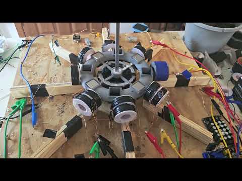 Long-form
2 circuits running a third room still for some growth/expansion.
Papa Bale here with a messy bench update.
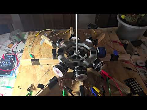 Long-form
M.P.H.'s pulse motor labs EP:2 Skin deep
I fire up two circuits at once, chase meter spikes, and retell the day a three magnet rotor one literally exploded at speed.
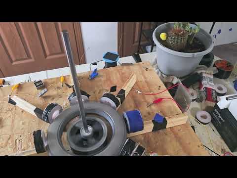 Long-form
Amp Funnel Coil: Pulse Motor Labs EP:1
Eight-magnet eight-coil pulse motor lab — amp funnel coil wiring, pickup coils, and give-and-take battery measurements.
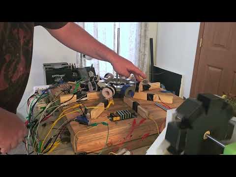 Long-form
MPH pulse motor lab
Real bench time with motor rotor magnets on a pulse motor rotor.
One path · free first
Watch free → subscribe → optional membership
Notes stay free. The full experiment lives on YouTube. Membership is optional when you want Discord and exclusives — not required to learn.
- 2
Subscribe free + turn on alerts
Hit Subscribe, then the 🔔 bell so you catch the next experiment.
Subscribe free + 🔔